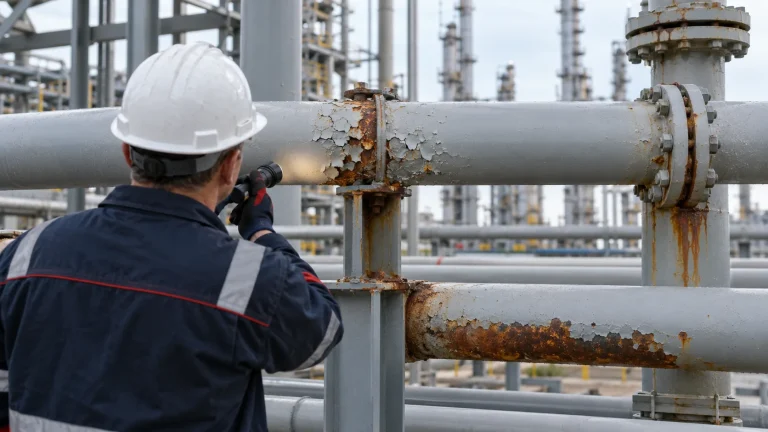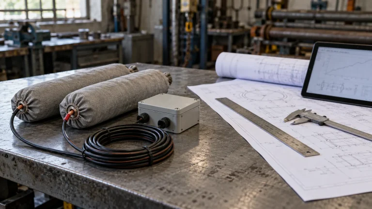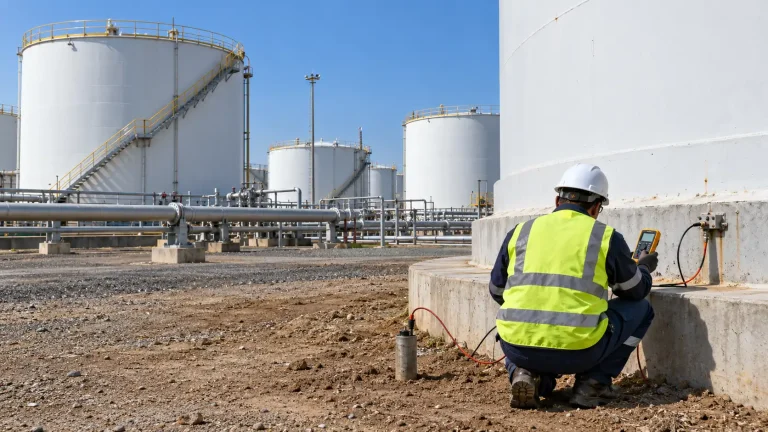
A cathodic protection system only works properly if the current goes exactly where it is meant to go. If the protected pipeline or tank is electrically connected to other metal structures, such as a plant’s earthing network, an old pipeline or another owner’s installation, part of that current leaks away, protection weakens and the system can even cause corrosion where there was none before.
This is where insulating joints come in: they are the components that prevent this problem. In this article we explain what an insulating joint is, what it does in a cathodic protection system, which types exist, where they are installed, how to check that they still insulate and what the most common failures of insulating joints for cathodic protection are.
What is an insulating joint
An insulating joint, also called a dielectric joint or electrical isolation joint, is a component fitted into a pipeline to break the electrical continuity between two sections without breaking their mechanical continuity or tightness. The fluid flows normally and the pipeline withstands the operating pressure, but electric current cannot pass from one side to the other through the metal.
To achieve this, the joint incorporates dielectric materials (resins, glass-fibre laminates, elastomers) between the two metal parts it connects. This creates an electrical boundary: the cathodically protected structure is on one side and, on the other, the installation that must not receive that current.
What an insulating joint does in cathodic protection
In cathodic protection, a structure is protected by making a direct current flow from anodes, through the soil, to the steel. That current is calculated for a specific surface. If the structure is connected to others, the current is shared among all of them and does not fully protect the one it was meant for. Insulating joints are used to:
- Define the protected structure. They set where the section that receives the current begins and ends, so that the system design matches the actual surface to be protected.
- Prevent current leaking to unprotected installations. Without isolation, current would escape to a plant’s copper earthing network, to reinforced concrete structures or to third-party pipelines. The system would need much more current and the anodes would be consumed sooner.
- Break galvanic couples. When buried steel is connected to copper or other more noble metals, a cell forms in which the steel corrodes faster. The joint breaks that connection.
- Divide a long network into sections. In gas and oil pipelines they allow protection to be sectorised, each section to be adjusted separately and problems to be located more easily.
- Limit interference and stray currents. Isolating the sections that run close to DC traction lines or other cathodic protection systems reduces the path of those currents along the pipeline.
- Separate installations belonging to different owners. For example, a distribution company’s network and an industrial customer’s internal installation, each with its own system and its own operator.
That is why, in the design of cathodic protection systems, locating the insulating joints correctly is as important as sizing the anodes or the transformer-rectifier.
Types of insulating joints for cathodic protection
There are three main solutions, chosen according to the diameter, the pressure, the fluid and the place where the joint is installed.
Monolithic or monoblock insulating joints
The monolithic insulating joint, known as a monoblock joint, is a factory-made component in which the two metal ends are joined and isolated from each other inside a closed body. It arrives on site pressure-tested and insulation-tested, and is installed by welding it into the pipeline like any other spool. It has no bolts or parts that can work loose, which makes it the preferred option in gas pipelines, oil pipelines and high-pressure networks, and the only suitable one when the joint has to be buried.
Insulating flanges or flange isolation kits
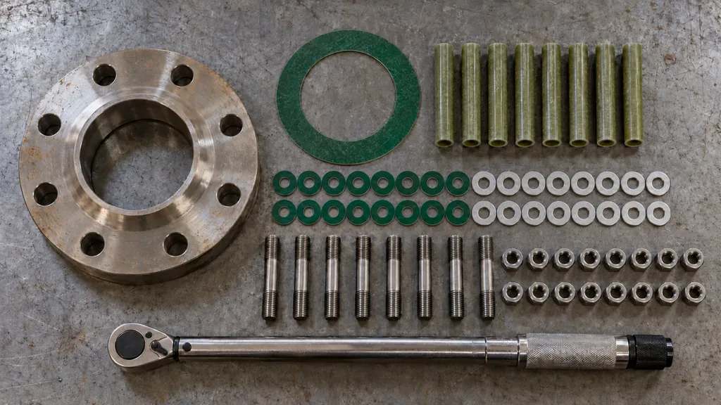
An insulating flange is assembled on two standard flanges with an isolation kit: a dielectric gasket between the flange faces, an insulating sleeve covering each stud bolt along its full length, and insulating washers, with their steel washer, under the nuts. In this way, no metal part connects the two flanges. It is an economical solution that is easy to install on existing pipelines, in pressure regulating and metering stations or at the entrance to a plant, but it needs careful assembly and must be in an accessible, dry location, because a single damaged sleeve or a little conductive dirt can bridge it.
Dielectric unions and sleeves for small diameters
In small-diameter pipes, such as service connections, instrument lines or the connections of fuel and LPG tanks, threaded dielectric unions or insulating sleeves are used. They perform the same function with much simpler installation.
| Criterion | Monolithic joint (monoblock) | Insulating flange (isolation kit) |
|---|---|---|
| Installation | Welded into the pipeline, no bolts | Bolted between two flanges, with insulating gasket, sleeves and washers |
| Reliability of the isolation | High: factory-tested and independent of site assembly | Depends on assembly and tightening; a damaged sleeve bridges it |
| Buried installation | Yes, with its external coating | Not recommended: better above ground or in an accessible pit |
| Pressure and diameter | Suitable for high pressure and large diameters | Common at low and medium pressure and in existing installations |
| Maintenance | Minimal: periodic check of the isolation | Inspection of sleeves and washers, cleaning and tightening |
| Cost | Higher component cost | Lower cost and quick installation on existing flanges |
Where insulating joints are installed
The general rule is to install an insulating joint at every point where the protected structure connects to something that must not receive the protection current. The most common cases are:
- At the inlet and outlet of stations for compression, pumping and pressure regulation and metering, which are usually connected to the installation’s earthing network.
- Where the pipeline comes out of the ground and continues above ground on metal supports or enters a building.
- At the connection with industrial plants, tanks or internal networks that have their own earthing.
- Between new and old sections, or between coated and bare pipelines, which need very different currents.
- Between installations belonging to different owners or with independent cathodic protection systems.
- On buried fuel tanks, between the tank and the pipes that connect it to the dispensers or to the building installation.
In the cathodic protection of pipelines over long distances, insulating joints are also used to divide the network into independent sections. In storage tanks and vessels, they separate the protected tank from the earthed pipes and equipment connected to it.
Besides the joint itself, you have to think about everything that could bridge it: metal supports, earthing cables of electrical equipment, valve actuators, instrument tubing or auxiliary pipes connecting both sides. If any of them electrically connects both sides, the joint no longer works even if it is in perfect condition.
Protecting the joint against overvoltages
An insulating joint separates two metal sections that, under normal conditions, only have a small potential difference between them. But lightning, a fault on a nearby power line or the voltage induced by a parallel high-voltage line can generate very high voltages between both sides. If they exceed the dielectric strength of the joint, they puncture it and leave it useless. On a gas pipeline, the electric arc can also be an ignition risk.
To prevent this, a surge arrester (spark gap) is installed in parallel with the joint. It does not conduct under normal conditions, but it closes when an overvoltage occurs and diverts it without damaging the joint. In areas with explosive atmospheres it must be a model certified for that purpose. Where alternating voltages are permanently induced, solid-state decouplers are used, which let alternating current pass but block the direct current of the cathodic protection.
The fluid must also be taken into account. If the pipeline carries water or another conductive liquid, the current can bypass the joint internally and corrode the inner wall of the pipe next to it. In these cases, a section on each side of the joint is internally coated to lengthen that path.
How to check an insulating joint
An insulating joint can stop insulating without any visible sign, which is why checking it is part of any survey of a cathodic protection system. These are the usual tests:
- Insulation resistance test before installation. With a DC insulation tester (megohmmeter), at the voltage set in the specification. Monolithic joints are also pressure-tested and dielectric-strength-tested at the factory. Once the pipeline is buried, this measurement is no longer representative, because both sides are connected through the soil.
- Potential measurement on both sides of the joint. With a reference electrode in the same position, the pipe-to-soil potential is measured on the protected side and on the unprotected side. If the joint insulates, the protected side will be much more negative than the other. If both read practically the same, the joint is bridged or punctured.
- On/off cycling test. By interrupting the transformer-rectifier cyclically, the potential on the protected side changes with each cycle while that of the unprotected side hardly moves. If both sides change at the same time, current is passing through the joint or through something that bridges it.
- Insulating joint tester. Specific instruments that, applied to both sides of the joint, show whether there is electrical continuity even when the pipeline is buried and connected to the soil.
- Inspection of each stud bolt on insulating flanges. This checks that none of them touches both flanges and that sleeves and washers are complete and in good condition.
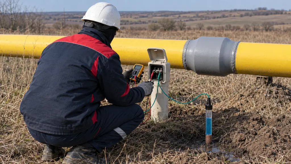
To be able to take these measurements, a test point with cables connected to both sides is installed next to each insulating joint. The check is carried out at least at every periodic survey of the system and also after storms, nearby works or any change to the installation. It is one of the tasks of our cathodic protection system inspection service.
Common failures of insulating joints
Most of the isolation problems we find during inspections are repeated from one installation to another:
- External metal bridges: an earthing cable, a support, a valve with its actuator or an auxiliary pipe connecting both sides of the joint, often added years later during an extension.
- Damaged or missing sleeves or washers on insulating flanges, due to incorrect assembly, parts not replaced when the flange was dismantled or overtightening that breaks the dielectric material.
- Moisture, dirt or conductive deposits on the flange surface or in a flooded pit, which create a path for the current.
- Puncture by overvoltages on joints without a surge arrester, after lightning or an electrical fault on a nearby line.
- Current passing internally when the fluid is conductive or sludge and sediment build up inside the pipe next to the joint.
- Corrosion on the unprotected side. Even if the joint insulates well, part of the protection current can enter the unprotected pipe through the soil and leave it right next to the joint to reach the protected side. At that exit point, the unprotected pipe corrodes. It is prevented by properly coating a section on each side and checking interference at the design stage.
A joint in poor condition shows symptoms in the measurements: the rectifier current has to be increased to maintain the same potentials, the anodes are consumed faster than expected or areas of the pipeline no longer meet the protection criterion. When that happens, the joint is one of the first points to check.
Insulating joints and cathodic protection with Procainsa
Since 1988 we have designed, installed and maintained cathodic protection systems for pipelines, gas pipelines, tanks and buried structures, with a NACE-certified technical team. In each project we define where the insulating joints should go and how to protect them, we supply dielectric joints and the rest of the system materials, and we check their isolation during periodic surveys, following standards such as ISO 15589-1 and NACE SP0286 on the electrical isolation of cathodically protected pipelines.
Frequently asked questions about insulating joints
Is an insulating joint the same as a dielectric joint?
Yes. Insulating joint, dielectric joint and electrical isolation joint are used for the same thing: a component that breaks the electrical continuity of the pipeline. Sometimes only the flat gasket fitted between the flanges, which is one of the parts of the isolation kit, is called a «dielectric gasket».
Which is better, a monoblock joint or an insulating flange?
It depends on the installation. The monoblock joint is more reliable, does not depend on site assembly and can be buried, which is why it is preferred in gas pipelines and high-pressure networks. The insulating flange is cheaper and more practical in existing installations and in stations, provided it is accessible and in a dry place.
Can an insulating joint be checked with a multimeter?
Not reliably when the pipeline is buried. Both sides of the joint are in contact with the soil, which connects them electrically, and the multimeter will measure that resistance even if the joint is fine. That is why it is checked by measuring the potentials on both sides, with on/off cycling of the rectifier or with a specific insulating joint tester.
Can an insulating joint be buried?
Monolithic joints can, with their external coating and a test point to measure both sides. Insulating flanges are best left above ground or in an accessible, dry pit, because they need inspection and moisture and dirt can bridge them.
How often should insulating joints be checked?
At least at every periodic survey of the cathodic protection system, which is usually annual. They should also be checked after storms with nearby lightning strikes, after works on the installation or after any change that could have created an electrical bridge.
Do you have doubts about the isolation of your installation? Our technical team checks your insulating joints and your cathodic protection system and proposes the necessary improvements. Request information.